
Our original plan, Plan "A", was to assemble the parts we needed to build an RO water maker of our own design. Last year Providence guided us to a complete RO system that had been removed from a boat being prepped for an Atlantic crossing. Rebuilding this used system and modifying it for our situation is Plan "B".
Now, a year later, we're living ashore part time and I finally have some real time to invest in this project. Good thing too because we'll definitely need it when we go to the Bahamas this winter. Time to get back to work. The system is 11 years old so parts of it need to be replaced but everything was supposedly in working condition three years ago. The Sea Recovery (click here) dealer in Annapolis came through with an owners/installation manual and a rebuild kit for the high pressure pump. I'm not planning to use the original feed pump because it draws too much power and will require periodic service. Instead I'll use the Iwaki fish tank pump I had purchased for my home grown system. The original membranes and housings were in bad shape so I tossed them after stripping off all the fittings and hardware. Replacing these is now the biggest expense for this system. I decided to increase the fresh water output from 24 to 40 gph by using two 2.5" x 40" membranes (FilmTec SW30-2540, $170 each) and housings (HCTI PV-2540-SW, $395 each). Most of the fittings on the old membranes were brass and I wanted to use stainless steel so I had to replace those too along with a new high pressure hose to join the two membranes in series. I got all these parts from Discount Hydraulic Hose (click here) and McMaster Carr (click here). The stainless fittings are pricey but I got everything I needed for about $200. The 1/2" high pressure hoses I got with the original system are all in very good condition and have stainless swivel connecters. All the low pressure tubing and plastic fittings for the product water are also in very good condition. The braided 3/4" hose for the feedwater is looking kinda sad so I'll replace that but reuse the fittings and clamps. There are several relays that I'll reuse if they still work but I'll probably back them up with replacements just in case. The system also included several nice two and three-way valves that I'll clean up and reuse.
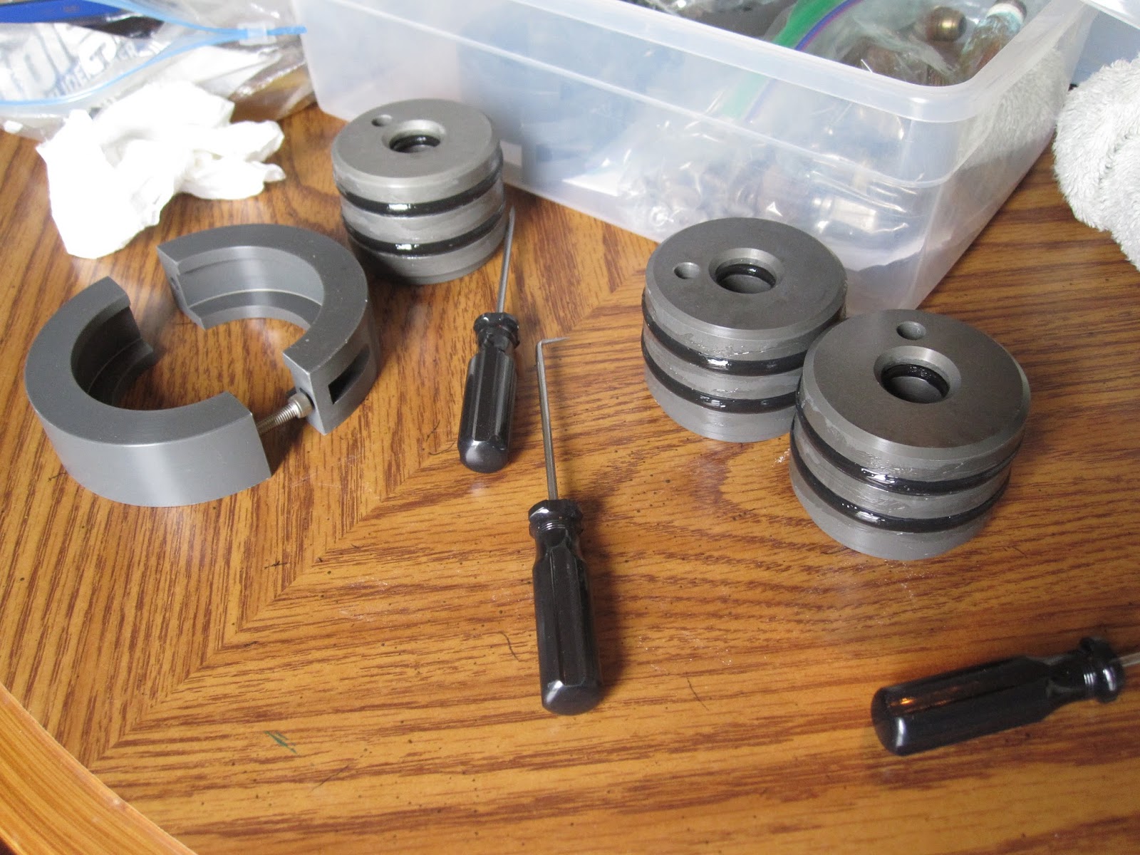

I've had the new membranes and housings since last February. These don't come with any assembly instructions so I spent some time on the net hunting for info. Found this paper from FilmTec (click here) which was a help. The end pieces for the membranes are anodized aluminum with three "O" rings at each end, two on the outside surface and one where the membrane nipple gets inserted. The end that goes toward the high pressure pump also has a brine seal on the membrane. The "O" rings need to be lubricated with silicone or glycerine or you'll never get them into the housings. The membranes come packed in a sealed bag with hydrogenated water or some such thing to keep them moist and well preserved. Rinse out the housings (not the membranes) to clear any dust and particulate matter. Mount one end piece on the intake side of the membrane and slide it into the housing from either end. The end piece has to be tapped into place with a rubber mallet so only the flange extends past the end of the housing. Two anodized aluminum half shells clamp over the end of the housing and hold the membrane firmly in place. The other end piece is installed from the other end, tapping it in place and securing with the half shell clamps.
With the membrane housings put together I next assembled the fittings and connector hose. The fittings I got are reusable and fairly easy to assemble. They come in two pieces. Installation requires a vise and wrench. Separate the two pieces of the fitting and secure the socket end into the vise. Lubricate the hose and screw it into the socket conterclockwise until it bottoms out, then back out a 1/2 turn. Next lubricate the nipple part of the fitting and screw it into the other end of the socket using a wrench until the hex shoulder is against the socket.


For now, it feels good to be back into this project. I plan to break it down into sub-assemblies mounted to plywood so when the time comes for installation on the boat it should go fairly smoothly. Originally I was going to mount everything in the chain locker and under the sole in the forward cabin. Plan B now has the membranes, filters and control panel mounted in the aft head and the pumps mounted behind the cabinets in the Main Salon.
More info to follow as progress is made.
More info to follow as progress is made.